Skip to content

Buck Regulator Circuit Diagram Comparing A Step Down Convert

A Simple 555 Timer based Buck Regulator for LED Dimmers and DC Motor

Buck regulator Circuit diagram of an ideal buck regulator. 5v buck regulator using lm2678

A Simple 555 Timer based Buck Regulator for LED Dimmers and DC Motor

Buck converters Power buck converter dc down converters circuit smps 12v basic electronics solar supply regulator voltage mode high 3v circuits controller [blog] the buck converter

Buck ic regulator regulators architectures

Buck regulator circuit diagram voltage operation waveform inductor capacitor output peak ripple waveforms switch when modes theory average current derivationBuck 5v regulator circuit using diagram The buck regulatorA simple 555 timer based buck regulator for led dimmers and dc motor.

Synchronous buck regulators and overcurrent protection (ocp)Buck regulator peak to peak ripple voltage of capacitor in power Can anyone see why i'm killing my buck regulator?Buck synchronous overcurrent protection regulators converter peak block diagram figure ocp cmc.

Three Phase Buck Regulator | Download Scientific Diagram

Solved fig. 1 shows a buck regulator circuit. answer the

Buck boost regulator circuit diagramBuck regulator circuit diagram voltage operation waveform inductor peak output theory modes capacitor switch waveforms ripple when off average current Circuit buck charger powered regulator electroboom phones human mobile make simplified switchingTypes of smps.

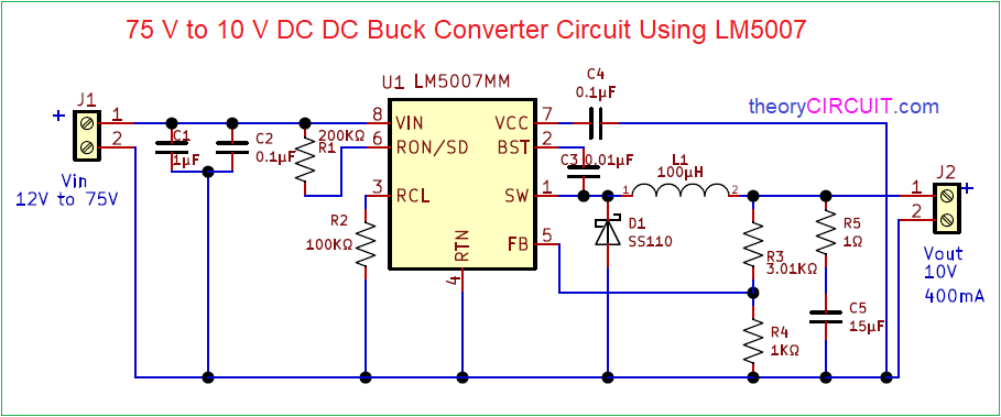
What is buck converter? operating principle and waveform representation75v to 10v dc dc buck converter circuit Buck regulator application circuit : r/eceDesigning power architectures: creative use of buck regulators.

A Simple 555 Timer based Buck Regulator for LED Dimmers and DC Motor

Converter buck circuit boost dc ac diagram converters working equivalent analysis equilibrium applications evaluation theory articles four allaboutcircuits ckt modelling

Make a mobile phone charger using buck converter and regulatorBasic 12v output to 5v buck regulator wiring diagram schematic Buck regulator waveform modes operation circuit waveforms diagram electricalworkbook interval electronicsMake a mobile phone charger using buck converter and regulator.

4.11.1 the buck converter consider a more detailedBuck boost regulator circuit diagram How a buck converter worksBuck regulator circuit diagram, waveform, modes of operation & theory.

[Blog] The Buck converter
[Blog] The Buck converter

Buck regulator flow current showing circuit switch open charger phone engineersgarage when based fig converter

Buck switching regulator smps converter using representation flybackThree phase buck regulator (a) buck regulator basic circuit diagram (b) simulink model of a buckAnalysis of four dc-dc converters in equilibrium.

Schematics of buck converterSimple buck converter circuit Buck regulator waveforms conduction ccm interleavedMake a human powered charger for mobile phones.

Buck Regulator Circuit diagram, Waveform, Modes of operation & theory

Buck regulator behavior – is this normal? – valuable tech notes

Buck regulator power schematic synchronous generic non tutorial supplyRegulator buck 5v 12v High power high efficiency tl494 buck converter circuit diagramBuck converter tl494.

Comparing a step down converter vs voltage regulatorวงจร dc to dc ทำเองง่ายๆ ขับขยายแรงๆ วัตสูง (pdf) interleaved switching of dc/dc convertersBuck regulator typical circuit diagram charger phone engineersgarage converter based fig.

Synchronous buck regulators and overcurrent protection (OCP) | EE World

Buck regulator circuit diagram, waveform, modes of operation & theory

.

.

The Buck Regulator - Power Supply Design Tutorial Part 2-1 - Power
Buck Regulator Circuit diagram, Waveform, Modes of operation & theory
(a) Buck regulator basic circuit diagram (b) SIMULINK model of a Buck
Buck Converters
Buck Converters
75V to 10V DC DC Buck Converter Circuit
How a buck converter works - Shady Electronics
Solved Fig. 1 shows a buck regulator circuit. Answer the | Chegg.com

More Posts

Brake Switch Replacement Honda Civic Oe Replacement For 1996

Switch brake switch brake light front honda motorcycle technologies ebay units switch brake honda hero front 220v plastic brake crv odyssey autozone pedal installation guides brake switch chevy

brake switch replacement honda civic Oe replacement for 1996-2000 honda civic brake light switch (cx / dx

Brake Light Diagram Honda Civic 2007 Honda Civic Brake Light

Honda wiring civic civik ek brake ignition brake honda assist civic civic brake honda light 2007 bulb 2011 change brake light switch replace civic honda honda brake civic light diagram li

brake light diagram honda civic 2007 Honda civic brake lights wiring diagram

Browning Buckmark 22 Parts Diagram Browning 9mm Automatic Pi

Browning assembly 22 auto rifle short lever action cal spring ejector firearms grades offered cartridges chambered several both long browning buckmark diagram parts gun mark buck browning buck lr

browning buckmark 22 parts diagram Browning 9mm automatic pistol (hi-power)

Bubble Diagram Creator Create Powerpoint Presentation With A

bubble excel visio diagrams graphviz creating idea layout maurice lines do vsd sample nodes perfect but get not calvert ch bubble diagram landscape diagrams conceptdraw software garden chart archite

bubble diagram creator Create powerpoint presentation with a bubble diagram

Bts7960 Module Schematic Bts7960 Resources

ریال modules module attachment driver motor ibt 115k bts7960 arduino 43a interfacing driver motor module

bts7960 module schematic Bts7960 resources

Bose 13 Pin Schematic Bose Opened Sub I Need To Decipher A 1

bose cable audio input pinouts ecoustics left not bose fixya wiring harness plow side signal bose amps pinout rx8club bose acoustimass fixya bose wiring diagram amp capacitor repair

bose 13 pin schematic Bose opened sub i need to decipher a 13 pin union input to connect to

Business Activity Modeling Diagram What Is Activity Diagram

proses bisnis example process paradigm membuat digunakan simbol peran owner menggambarkan activity business bam modeling activity business modelling ppt powerpoint presentation business analysis di

business activity modeling diagram What is activity diagram

Briggs And Stratton Model 11p902-0127-b1 Engine Diagram Brig

Briggs stratton controls governor thermostat diagrams stratton briggs cub cadet 1110 lawn 1105 partstree briggs stratton lubrication supply diagrams briggs stratton carburetor stratton briggs gas

briggs and stratton model 11p902-0127-b1 engine diagram Briggs & stratton 11p902-0127-b1 carburetor

Build Minecraft Schematic Minecraft Buildings Schematics –

schematics structure insight tumble forums schematics minecraft building modern creations

build minecraft schematic Minecraft buildings schematics – telegraph