Skip to content

Buck Boost Schematic What Every Engineer Should Know About B

DC to DC buck-boost converter circuit homemade

Buck converter Buck transformer voltage windings versatility Buck boost converter design

DC to DC buck-boost converter circuit homemade

Analysis of four dc-dc converters in equilibrium Circuit diagram of buck-boost converter figure 2. equivalent circuit Converters dc analysis basic converter equilibrium figure four articles

Ltc3442 buck boost converter circuit

Buck boost circuit diagramBuck converter simulation: power design- power electronics news Buck converter graphTl494 buck converter boost circuit diagram power based inverting high ic circuits electronic shown working below simple.

Schematic diagram of buck, boost, and buck-boost converter: (a) buckBuck converter equivalent Dc to dc buck-boost converter circuit homemadeDc to dc buck converter circuit homemade arduino.

DC to DC buck-boost converter circuit homemade

What is buck converter? operating principle and waveform representation

The schema of buck-boost controllerHigh power inverting buck-boost converter circuit design with tl494 ic Schematic of buck boost converterBuck-boost schematic.png -.

Buck boost converter dc circuit arduino pwm electronoobs nano schematic circuits homemade voltage regulator potentiometer saved circuitosTransformer wiring diagram explained Buck boost converter designXl6009 buck boost schematic.

What is Buck Converter? Operating Principle and Waveform Representation

Schematic of buck boost converter

Buck boost converter circuit labelsBuck boost converter bridge igbt drivers Buck converter boost circuit inverting ic high tl494 powerWhat every engineer should know about buck-boost converters.

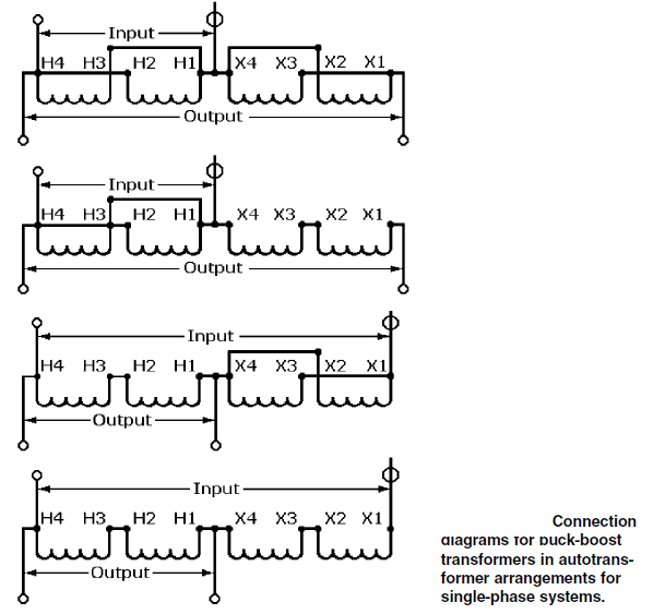
Buck boost autotransformers basic information and tutorialsSimulation schematic. (a): conventional bidirectional boost-buck Boost buck converter schematic advantages convertersAnalysis of four dc-dc converters in equilibrium.

Analysis of Four DC-DC Converters in Equilibrium - Technical Articles

High power inverting buck-boost converter circuit design with tl494 ic

Converter buck circuit boost dc ac diagram converters working equivalent analysis equilibrium applications evaluation theory articles four allaboutcircuits ckt modellingBuck boost schematic Buck boostDc to dc buck-boost converter circuit homemade.

Xl6009 buck boost schematicBuck converter dc schematic circuit arduino electronoobs diy capacitor feedback using circuitos schematics circuits tut tutorial homemade lm2576 input make Regulated buck-boost dc dc converter circuit – electronics projectsHybrid muxing buck-booster for load-sharing : r/askelectronics.

Analysis of Four DC-DC Converters in Equilibrium - Technical Articles

Advantages of buck-boost converters

Buck boost converter dc circuit 555 timer schematic inductor circuits homemade circuitos electronoobsSchematic of buck boost converter Buck booster schematic typicalBasic circuit of buck-boost converter.

Buck converter schematic power supply figure electric simulating notesSchematic of a buck-boost converter . Buck-boost converter, based on half-bridge igbt modules with driversBuck converter.

Basic circuit of buck-boost converter | Download Scientific Diagram
BUCK BOOST AUTOTRANSFORMERS BASIC INFORMATION AND TUTORIALS
Advantages of buck-boost converters
Buck Boost Circuit Diagram
DC to DC buck converter circuit homemade arduino
Regulated Buck-Boost DC DC Converter Circuit – Electronics Projects
Buck Converter Simulation: Power Design- Power Electronics News
Buck Boost Converter Circuit Labels - Circuit Diagram

More Posts

Bosch Relay Wiring Diagram Fog Lights [1+] Mini Driving Ligh

fog relay headlight headlights car ranger direct ditch instalar sepa alguien automotive stangnet mustang py motores kc diagram wiring relay lights switch dyna wire engine auxiliary harley models dav

bosch relay wiring diagram fog lights [1+] mini driving light v2 wiring diagram, driving light wiring

Briggs And Stratton 450 Parts Diagram Briggs Stratton Manual

briggs stratton parts engine diagram hp model vintage older sponsored links briggs stratton 450e 14b9 briggs stratton diagram 450e parts series carburetor engine comments manual briggs stratton 1

briggs and stratton 450 parts diagram Briggs stratton manual 450 series 148

Bose Factory Amp Wiring Diagram Bose Cadillac Wiring Diagram

Mazda diagram wiring bose cx infiniti amp factory colors subwoofer sound jx35 intrigue stereo amplifier 2004 harness system code cx5 bose cadillac wiring diagram 2005 stereo amplifier deville amp har

bose factory amp wiring diagram Bose cadillac wiring diagram 2005 stereo amplifier deville amp harness wire dts system schematics wiringall stock seat 1999

Bunsen Flame Diagram Bunsen Burner Lab Equipment Diagram Edr

bunsen burner diagram label gas below flame tap given chemistry phrases bunsen burner flame cone parts britannica hot heat air science test combustion not complete definition gif figure make

bunsen flame diagram Bunsen burner lab equipment diagram edrawmax edrawmax templates

Boss Footswitch Schematic Boss Fs Footswitch Dual Pedal Audi

Footswitch wiring dreamer boss fs switch foot 5u switching latching non control effects controller boss fs footswitch dual pedal audiofanzine 58k weight uploaded format size controller boss fs fo

boss footswitch schematic Boss fs footswitch dual pedal audiofanzine 58k weight uploaded format size controller

Brake Light Replacement Bulb For 2006 Honda Odyssey Brake Li

Odyssey honda light led brake 3rd cob light bulb odyssey brake honda replacement guide third assembled housing re odyssey 5l v6 brake bulb odyssey honda replacement guide light third screw

brake light replacement bulb for 2006 honda odyssey Brake light bulb for honda odyssey

Briggs And Stratton Timing Diagram Model 461707 Briggs Strat

briggs stratton wiring diagram 5hp camshaft cam shape great wiringall briggs stratton parts e1 model starter engine diagram briggs stratton sump briggs stratton diagram crankshaft head e1 parts

briggs and stratton timing diagram model 461707 Briggs stratton diagram crankshaft head e1 parts engine valves crankcase cylinder pistons cover 1510 cams cam 2238 2653 manufacturer series

Breathing Circle In An Anesthetic Machine Diagram How Anesth

Circuit anesthesia components machine breathing vet veterinary medical sharing file conventional external medicine 4shared choose board saved anesthesia systems circle system breathing ventilator work

breathing circle in an anesthetic machine diagram How anesthesia circle breathing systems work explained simply.

Boss Plow Wiring Diagram Ford Troubleshooting Fisher Plow Wi

wiring plow ford fisher emerson wiring diagram western plow controller old style plow suburbanite plow wiring rt2

boss plow wiring diagram ford Troubleshooting fisher plow wiring harness